Experiment 1 - No Load Test of a 3-Phase Induction motor
LEARNING OUTCOMES
Control of three-phase A.C. wound-rotor induction motors.
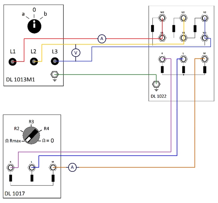
EQUIPMENT:
A slip ring three-phase asynchronous motor (DL 1022).
1.1kW Unilab power supply (DL 1013M1).
3x 1kW resistive load (DL 1017).
3x digital multimeter (Fluke 117).
Matrix terminal.
A digital tachometer (non-contact, Extech 461700).
PROCEDURE:
- Connect the machines and equipment as shown in Figure 1.
- Record the ratings of the asynchronous machine shown at the name plate in Table 1. These ratings must not be exceeded at any time throughout the duration of the experiment.
- Ensure that the SAFETY key, circuit breakers and switches are activated; "START" push button switched off (inactive).
- Turn on the voltmeter and ammeters (by selecting the appropriate range) and adjust the dial of the resistor to a maximum value.
- Set the variable AC voltage control knob on the power supply to minimum (zero).
- Standby for instructor's approval to commence the experiment.
| Parameter | Value |
|---|---|
| Voltage (V) | |
| Current (I) | |
| Speed (rpm) |
EXPERIMENT 1A: Measurement of no-load characteristic curves
Note: Record the speed, voltage, and current(s) in Table 2 for every voltage increment and resistor values within 2 seconds.
- Turn on the variable AC voltage switch (press "START" button). Then, slowly turn up the variable AC voltage STARTING FROM 0V to 220V; in steps of 40V.
- Continuously monitor the no-load current of the induction motor at every voltage range.
- Gradually reduce the resistance from maximum to position 4 (and record all relevant parameters in Table 2) and return the dial to maximum position before proceeding to the subsequent voltage range.
- Upon completion, reduce the variable AC voltage to 40V before pressing "STOP" button.
| Rmax | R2 | R3 | R4 | ||||||||
|---|---|---|---|---|---|---|---|---|---|---|---|
| Voltage (V) | Current (A) | Speed (rpm) | Voltage (V) | Current (A) | Speed (rpm) | Voltage (V) | Current (A) | Speed (rpm) | Voltage (V) | Current (A) | Speed (rpm) |
EXPERIMENT 1B: Short-circuit test of asynchronous slip ring induction motor
NOTE: Wait for instructors' approval before initiating a short circuit and immediately undo the experiment the upon obtaining the current reading (less than two seconds).
- Continuing from the previous experiment, set the resistance is set to zero.
- Press "START" button.
- Record all relevant parameters in Table 3.
- Return the dial to maximum position and press the "STOP" button.
| V₀ (V) | I₀ (A) | I (A) | N (rpm) |
|---|---|---|---|
EXPERIMENT 1C: Open-circuit test of asynchronous slip ring induction motor
NOTE: Wait for instructors' approval before initiating a short circuit and immediately undo the experiment the upon obtaining the current reading (less than two seconds).
- Disconnect the rotor winding from the variable resistor (place it in a matrix terminal).
- Turn on the variable AC voltage switch (press "START" button). Then, slowly turn up the variable AC voltage to 80V.
- Continuously monitor the rotor current (IA) of the induction motor.
- Record all relevant parameters in Table 4.
- Ensure that the resistance is at maximum position and the variable AC voltage is brought to zero and press the "STOP" button.
- Ensure that the switches, circuit breakers and SAFETY key are de-activated.
- Turn the voltmeter and ammeters OFF
| V₀ (V) | I₀ (A) | I (A) | N (rpm) |
|---|---|---|---|
ASSESSMENT MARKING SCHEME: EXPERIMENT 1
| Practical Details | Enabling Objectives | Maximum Possible Marks |
|---|---|---|
| Practical | ||
| 1. Connect the motor to power supply (delta configuration) | 2.2.2. Explain with diagram the operation of wound-rotor type induction motors. | 12 |
| a) Connect power supply to motor (0V – 240V) | 2.2.2. Explain with diagram the operation of wound-rotor type induction motors. | 12 |
| b) Stator winding in delta formation. | 2.2.2. Explain with diagram the operation of wound-rotor type induction motors. | 12 |
| c) Voltmeter connection | 2.2.2. Explain with diagram the operation of wound-rotor type induction motors. | 12 |
| d) Ammeter (stator) connection | 2.2.2. Explain with diagram the operation of wound-rotor type induction motors. | 12 |
| 2. Connect the motor to power supply (delta configuration) | 2.2.2. Explain with diagram the operation of wound-rotor type induction motors. | 12 |
| a) Connect to rotor winding to variable resistors | 2.2.2. Explain with diagram the operation of wound-rotor type induction motors. | 12 |
| b) Ammeter (rotor) connection | 2.2.2. Explain with diagram the operation of wound-rotor type induction motors. | 12 |
| 3. Earthing connection | 2.2.2. Explain with diagram the operation of wound-rotor type induction motors. | 12 |
| 4. Turn on operation | 2.2.1. Verify, through experiment, how relevant parameters of the motor are affected by supply are affected by the speed controller. | 12 |
| 5. Turn on operation | 2.2.1. Verify, through experiment, how relevant parameters of the motor are affected by supply are affected by the speed controller. | 12 |
| Theory | ||
| 6. Fill in Table 1. | 2.2.1. Verify, through experiment, how relevant parameters of the motor are affected by supply are affected by the speed controller. | 3 |
| 7. Fill in Table 2. | 2.2.1. Verify, through experiment, how relevant parameters of the motor are affected by supply are affected by the speed controller. | 48 |
| 8. Fill in Table 3. | 2.2.1. Verify, through experiment, how relevant parameters of the motor are affected by supply are affected by the speed controller. | 4 |
| 9. Fill in Table 4. | 2.2.1. Verify, through experiment, how relevant parameters of the motor are affected by supply are affected by the speed controller. | 4 |
| TOTAL | 167 | |
Performance Standard: 1. Given variable three-phase A.C. power supply, wiring diagrams, circuit components, electrical measuring instruments, and a tachometer, connect the circuits and operate a three-phase A.C. wound-rotor induction motor with speed control, quick-stop control and reversing direction capabilities within a specified time.
Experiment 2 - 3-Phase Alternator Operation at Below and Rated Speed
LEARNING OUTCOMES
Test voltage and frequency controller for three-phase synchronous generator.
EQUIPMENT:
Prime mover: A slip ring three-phase asynchronous motor (DL 1022).
Alternator: A three-phase synchronous machine (DL1026).
1.1kW Unilab power supply (DL 1013M1).
3x 1kW resistive load (DL 1017).
5x digital multimeter (Fluke 117).
Load bank.
A digital tachometer (non-contact, Extech 461700).
PROCEDURE:
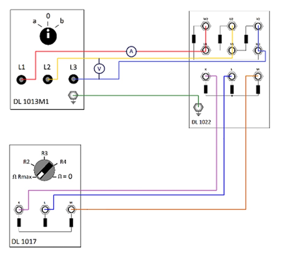
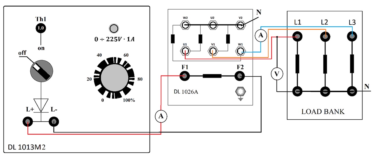
- Connect the machines and equipment as shown in Figure 1 and Figure 2.
- Record the ratings of the synchronous machine and asynchronous motor shown at the name plate in Table 1. These ratings must not be exceeded at any time throughout the duration of the experiment.
- Ensure that the SAFETY key, circuit breakers and switches supply are activated; "START" push button switched off (inactive).
- Turn on the voltmeter and ammeters (by selecting the appropriate range).
- Adjust the dial of the variable resistor to maximum resistance value.
- Set the variable AC voltage control knob on the power supply to minimum (zero).
- Standby for instructor's approval to commence the experiment.
- Turn on the variable AC voltage switch (press "START" button). Then, slowly turn up the variable AC voltage and raise the prime mover's terminal voltage from 0V to 220V.
- Note: Ensure that voltage, and current(s) of the prime mover does not exceed its rated parameters
| Parameter | Value |
|---|---|
| Voltage (V) | |
| Current (I) | |
| Speed (rpm) |
EXPERIMENT 2A: Measurement on loaded condition of an alternator below its rated speed.
- Switch on the variable DC - excitation power supply.
- Slowly increase the generator's excitation field to raise alternator voltage output from 50V to 200V in steps of 50V.
- Record your findings in Table 2.
- Slowly reduce the generator's excitation field to 0V.
- Switch off the variable DC power supply.
EXPERIMENT 2B: Measurement on loaded condition of an alternator at its rated speed.
- Gradually reduce the variable resistance from maximum resistance to short circuit.
- Repeat step 8 – 10.
- Slowly reduce the generator's excitation field from to 0V and switch off the variable DC power supply.
- Return the resistance at it's maximum value and reduce the prime mover's terminal voltage to 0V.
- Press the "STOP" button and ensure that the SAFETY key, circuit breakers and switches supply are de-activated.
- Turn the voltmeter and ammeters OFF.
| Below rated speed | At rated speed | ||||||
|---|---|---|---|---|---|---|---|
| VL (V) | IL (A) | IDC (A) | N (rpm) | VL (V) | IL (A) | IDC (A) | N (rpm) |
ASSESSMENT MARKING SCHEME: EXPERIMENT 2
| Practical Details | Enabling Objectives | Maximum Possible Marks |
|---|---|---|
| PRACTICAL | ||
| 1. Connect the motor to power supply (delta configuration) | 3.2.2 Investigate practically, the operation of an alternator voltage and speed controller. | 12 |
| a) Connect power supply to motor (0V – 220V). | 3.2.2 Investigate practically, the operation of an alternator voltage and speed controller. | 12 |
| b) Stator winding in delta formation. | 3.2.2 Investigate practically, the operation of an alternator voltage and speed controller. | 12 |
| c) Voltmeter connected to asynchronous motor terminal. | 3.2.2 Investigate practically, the operation of an alternator voltage and speed controller. | 12 |
| d) Ammeter connected to asynchronous motor terminal. | 3.2.2 Investigate practically, the operation of an alternator voltage and speed controller. | 12 |
| 2. Connect the rotor winding of the asynchronous motor to the variable resistors. | 3.2.2 Investigate practically, the operation of an alternator voltage and speed controller. | 12 |
| 3. Synchronous machine connection (star/wye configuration) | 3.2.2 Investigate practically, the operation of an alternator voltage and speed controller. | 12 |
| a) Stator winding in star formation. | 3.2.2 Investigate practically, the operation of an alternator voltage and speed controller. | 12 |
| b) De excitation connection. | 3.2.2 Investigate practically, the operation of an alternator voltage and speed controller. | 12 |
| c) Synchronous machine to load connection. | 3.2.2 Investigate practically, the operation of an alternator voltage and speed controller. | 12 |
| d) Voltmeter connected to load. | 3.2.2 Investigate practically, the operation of an alternator voltage and speed controller. | 12 |
| e) Ammeter connected to load. | 3.2.2 Investigate practically, the operation of an alternator voltage and speed controller. | 12 |
| a) Ammeter connected to DC exciter. | 3.2.2 Investigate practically, the operation of an alternator voltage and speed controller. | 12 |
| b) Neutral Connection | 3.2.2 Investigate practically, the operation of an alternator voltage and speed controller. | 12 |
| 4. Earthing connection | 3.2.2 Investigate practically, the operation of an alternator voltage and speed controller. | 12 |
| 5. Turn on operation | 3.2.2 Investigate practically, the operation of an alternator voltage and speed controller. | 12 |
| 6. Turn off operation | 3.2.2 Investigate practically, the operation of an alternator voltage and speed controller. | 12 |
| THEORY | ||
| 7. Fill in Table 1. | 3.2.2 Investigate practically, the operation of an alternator voltage and speed controller. | 3 |
| 8. Fill in Table 2. | 3.2.2 Investigate practically, the operation of an alternator voltage and speed controller. | 32 |
| TOTAL | 239 | |
Performance Standard: 1. Given a small-size three-phase A.C. generating set complete with auxiliary equipment, speed governor and voltage control gear, investigate the operation of an alternator voltage controller, speed governor and synchronising two alternators within a specified time.
Experiment 3 - Flux and Armature Control Operation of a DC Motor
LEARNING OUTCOMES
Determine the operating characteristics of D.C. motor.
Control of D.C. Motors
EQUIPMENT:
Edition DC compound Motor
1.1kW Unilab power supply (DL 1013M1).
2x 400W resistive load (DL 1017).
4x digital multimeter (Fluke 117).
A digital tachometer (non-contact, Extech 461700).
PROCEDURE:
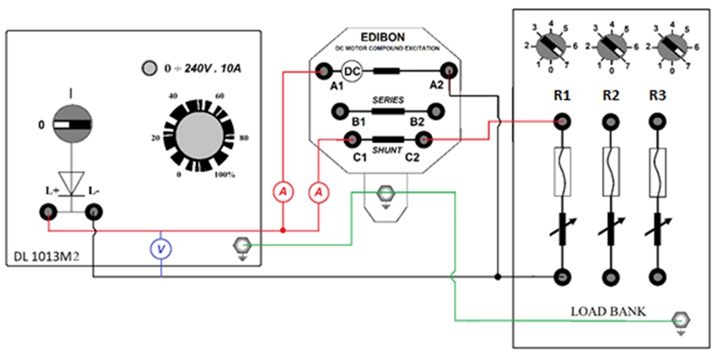
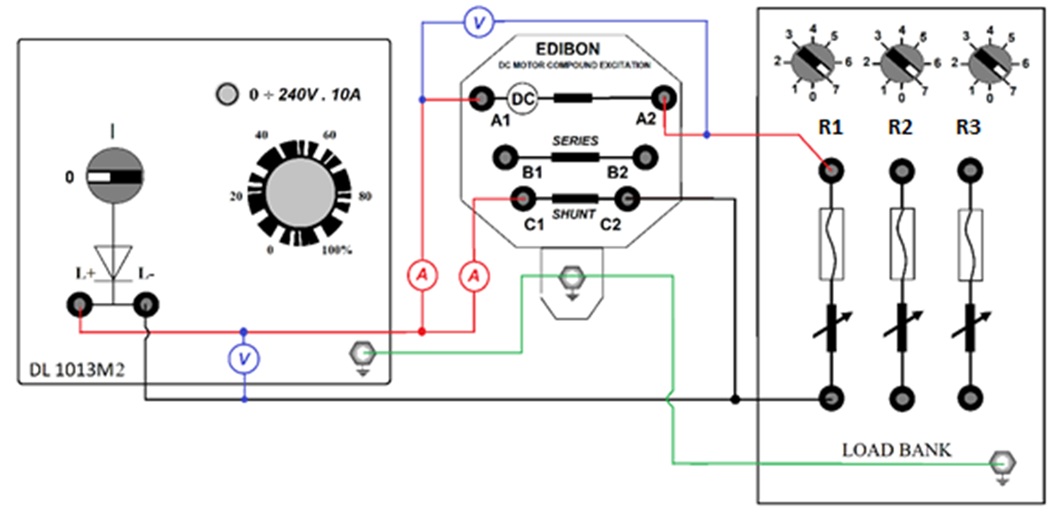
- Connect the machines and equipment as shown in Figure 1.
- Record the ratings of the DC motor shown at the name plate in Table 1. These ratings must not be exceeded at any time throughout the duration of the experiment.
- Ensure that the SAFETY key, circuit breakers and switches are activated; "START" push button switched off (inactive).
- Turn on the voltmeter and ammeters (by selecting the appropriate range) and adjust the dial of the resistor to a minimum value (setting no.7).
- Set the variable DC voltage control knob on the power supply to minimum (zero).
- Standby for instructor's approval to commence the experiment.
| Parameter | Value | Parameter | Value |
|---|---|---|---|
| Power | Speed | ||
| Armature (V) | Armature (I) | ||
| Excitation (V) | Excitation (I) |
EXPERIMENT 3A: Flux Control Method Operation
- Turn on the variable DC voltage switch (press "START" button). Then, slowly turn up the variable DC voltage to 200V.
- Gradually increase the resistance value (from position 7 to position 1).
- Record all relevant parameters in Table 2.
- Return the resistance (to lowest value by) setting to position 7.
- Slowly reduce the variable DC voltage to zero and press the "STOP" button (ensure all switches are not active).
| RESISTANCE (Ω) | Shunt Field Current, Ish (A) | Speed (N) |
|---|---|---|
| R7 | ||
| R6 | ||
| R5 | ||
| R4 | ||
| R3 | ||
| R2 | ||
| R1 |
EXPERIMENT 3B: Armature Control Method Operation
- Modify the circuit as shown in Figure 2.
- Turn on the variable DC voltage switch (press "START" button). Then, slowly turn up the variable DC voltage to 200V.
- Gradually increase the resistance value by shifting from position 7 to position 1.
- Record all relevant parameters in Table 3.
- Return the resistance (to minimum value by) setting to position 7.
- Slowly reduce the variable DC voltage to zero and press the "STOP" button (ensure all switches are not active).
| RESISTANCE (Ω) | Armature Voltage, VRa (V) | Speed (N) |
|---|---|---|
| R7 | ||
| R6 | ||
| R5 | ||
| R4 | ||
| R3 | ||
| R2 | ||
| R1 |
POST-OPERATION PROCEDURE:
- Return the switches to its neutral state (open) and deactivate all relevant circuit breakers (press the "OFF" button at main supply).
- Turn the SAFETY key OFF.
- Turn the voltmeter and ammeters OFF.
- Complete the experiments from collected data and answer in the provided sheets.
ASSESSMENT MARKING SCHEME: EXPERIMENT 3
| Practical Details | Enabling Objectives | Maximum Possible Marks |
|---|---|---|
| DC Shunt Motor (Flux Control) | ||
| 1. DC motor connection (Flux control) | 2.2.1. Illustrate the connections and explain the operational procedures for the following type of starters. | 12 |
| a) Connect power supply to motor (240V) | 2.2.1. Illustrate the connections and explain the operational procedures for the following type of starters. | 12 |
| b) Voltmeter (power supply) connection | 2.2.1. Illustrate the connections and explain the operational procedures for the following type of starters. | 12 |
| c) Ammeter (armature) connection | 2.2.1. Illustrate the connections and explain the operational procedures for the following type of starters. | 12 |
| d) Ammeter (shunt field) connection | 2.2.1. Illustrate the connections and explain the operational procedures for the following type of starters. | 12 |
| e) Earthing connection | 2.2.1. Illustrate the connections and explain the operational procedures for the following type of starters. | 12 |
| f) Load bank connection | 2.2.1. Illustrate the connections and explain the operational procedures for the following type of starters. | 12 |
| 2. Flux control operation | 2.1.2. Perform by determining the characteristic of the D.C. motor under control for shunt, series and compound D.C. motor. | 12 |
| DC Shunt Motor (Armature Control) | ||
| 3. DC motor connection (Armature control) | 2.2.1. Illustrate the connections and explain the operational procedures for the following type of starters. | 12 |
| a) Load bank connection | 2.2.1. Illustrate the connections and explain the operational procedures for the following type of starters. | 12 |
| b) Voltmeter (power supply) connection | 2.2.1. Illustrate the connections and explain the operational procedures for the following type of starters. | 12 |
| 4. Armature control operation | 2.1.2. Perform by determining the characteristic of the D.C. motor under control for shunt, series and compound D.C. motor. | 12 |
| THEORY | ||
| 5. Fill in Table 1. | 2.1.2. Perform by determining the characteristic of the D.C. motor under control for shunt, series and compound D.C. motor. | 6 |
| 6. Fill in Table 2. | 2.1.2. Perform by determining the characteristic of the D.C. motor under control for shunt, series and compound D.C. motor. | 14 |
| 7. Fill in Table 3. | 2.1.2. Perform by determining the characteristic of the D.C. motor under control for shunt, series and compound D.C. motor. | 14 |
| TOTAL | 176 | |
Performance Standard: Given the necessary technical information, D.C. machines, measuring and test instrument equipment. Determine the behaviour of D.C. machines by test and select the machines for specific applications within a specified time. Given a variable D.C. power supply, wiring diagrams, circuit components, multimeters, D.C. clamp-ammeters, and a tachometer, connect the circuits and operate the D.C. motors with speed control, quick stop control, and reversing direction capabilities within a specified time.